The Light Control System
This page provides some information about testing the ASM specification for the light control system. The implementation is a graphical user interface which allows interaction with the control system. You can enter rooms, switch light on and off, simulate malfunction of light sensors and motion sensors and so on.Implemented building
The ASM specification is designed for any building. However the building defined in this implementation consists only of one floor and eight rooms. Four rooms on the left side and the other rooms on the right side. You are free to create other buildings. In this case you have to modify the corresponding definitions in basic/exampleDefs.gsEach room and the hallway section has one motion sensor. Four rooms together has a light sensor. There is one light sensor for the rooms on the left side and another sensor for the rooms on the right side of the floor.
Information about starting
We assume that you can start AsmGofer and downloaded the example. Your current working directory should contain the following files:README lib/List.gs core/types.gs basic/types.gs basic/instances.gs basic/constants.gs basic/exampleDefs.gs basic/staticDefs.gs basic/internalState.gs basic/state.gs basic/defs.gs core/rules.gs gui/main.gs light.pStart AsmGofer and load the project light.p
joe@venus:~/asm/light > asmgofer
=== AsmGofer v1.0.1 (TkGofer v2.0) ===
(with modules: guiMonad, widget, time, io, concurrent, asmvar)
Gofer Version 2.30a  Copyright (c) Mark P Jones 1991-1994

Reading script file "/home/joe/cvs_eth/AsmGofer/Preludes/tk.prelude-all-asm":

Gofer session for:
/home/joe/cvs_eth/AsmGofer/Preludes/tk.prelude-all-asm
Type :? for help
? :p light.p
...
? main
After typing main the graphical user interface will appear.
Description of the GUI
The main user interface consists of three windows: The malfunction database, the control window and the building.
 Malfunction database
The malfunction database contains
all malfunctions and is updated after pressing the update
button or after 10 seconds.
Malfunction database
The malfunction database contains
all malfunctions and is updated after pressing the update
button or after 10 seconds.
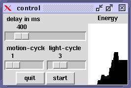 With the control window you can start and stop the simulation by pressing
the start button. The text on the button switches between start
and stop respectively. The scaler for delay in ms controls the
main speed and motion-cycle and light-cycle determines
when the corresponding rules will be called. A value of 1 means
each cylce, a value of 2 only every second cycle and so on.
The window shows also the energie consumption.
With the control window you can start and stop the simulation by pressing
the start button. The text on the button switches between start
and stop respectively. The scaler for delay in ms controls the
main speed and motion-cycle and light-cycle determines
when the corresponding rules will be called. A value of 1 means
each cylce, a value of 2 only every second cycle and so on.
The window shows also the energie consumption.
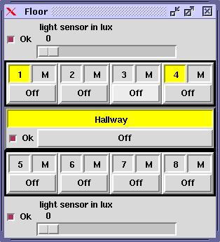 Floor window
The Floor window allows to interact with the control system. The rooms
are numbered from 1 to 8. Clicking the corresponding
number opens a new window. The room window is described below.
Floor window
The Floor window allows to interact with the control system. The rooms
are numbered from 1 to 8. Clicking the corresponding
number opens a new window. The room window is described below.
Each room has its own list of malfunctions. This list is accessible by
pressing the M right to the corresponding room number in the
Floor window. Under the room number there is a Off button.
This is the manually switch off button for the facility manager. Please
notice that the light could only be turned off if the room is not
occupied. Room occupation is denoted by a yellow background for the
room number.
There are two scalers for the light sensors. Each light sensor has a check
button determing whether the sensor works correctly (marked).
There is one remaining check button determing whether the hallway button
works correctly. The hallway can be controlled in the same way
as rooms.
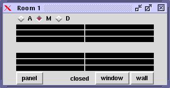 Room window
On the top or bottom you can either see a button labeled
with closed or open. This button displays the current
state of the door to the hallway section. You can switch the state by
pressing the button.
Room window
On the top or bottom you can either see a button labeled
with closed or open. This button displays the current
state of the door to the hallway section. You can switch the state by
pressing the button.
There are three other buttons panel,
window and wall. Pressing the button
panel opens the control panel for the room.
The buttons window and wall
are the wall switches for the ceiling lights. The illuminance of the
lights are shown in the middle of the window. We have six wall ceiling
lights and six window ceiling lights. Initially all lights are
black (off).
The motion sensor is realized by three radio buttons. State
A means always motion, M only motion when clicking and
D is a defect motion detector. If you change the mode to M
and the simulation is running then for instance the default light scene
should be activated.